
TM 5-2410-241-23-2
0193
INSTALLATION
000193
N OT E
Install hose as noted in removal.
1. Position hose (Figure 3, Item 5) on machine.
2. Install new preformed packing (Figure 3, Item 9) on hose (Figure 3, Item 5).
3. Install hose (Figure 3, Item 5), four washer (Figure 3, Item 7), and bolts (Figure 3, Item 6) on main hydraulic
control valve (Figure 3, Item 8).
4. Install grommet (Figure 3, Item 4) and two spring tension clips (Figure 3, Item 3) on hose (Figure 3, Item 5).
5. Install two spring tension clips (Figure 3, Item 3), washer (Figure 3, Item 2) and nut (Figure 3, Item 1) on hose
(Figure 3, Item 5).
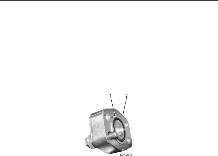
6. Install new O-ring (Figure 4, Item 1) on hose (Figure 4, Item 2).
Figure 4. Flange.
0193