
TM 5-2410-241-23-3
0211
DISASSEMBLY
000211
N OT E
Note orientation and position of fittings andvalves to aid assembly.
Tag and mark all fittings andvalves to aid installation.
Clean exterior of component to prevent contamination.
Plug all fitting ports to prevent contamination and leaks.
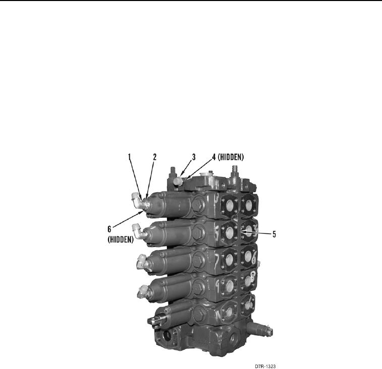
1. Loosen 10 nuts (Figure 7, Item 2) and remove 10 elbow fittings (Figure 7, Item 1) and O-rings (Figure 7, Item 6)
from control valve assembly (Figure 7, Item 5). Discard O-rings.
2. Remove fitting (Figure 7, Item 3) and O-ring (Figure 7, Item 4) from control valve assembly (Figure 7, Item 5).
Discard O-ring.
Figure 7. Control Valve Assembly.
0211