
TM 5-2410-241-23-3
0211
REMOVAL CONTINUED
N OT E
Tag and mark all hoses and lines to aid installation.
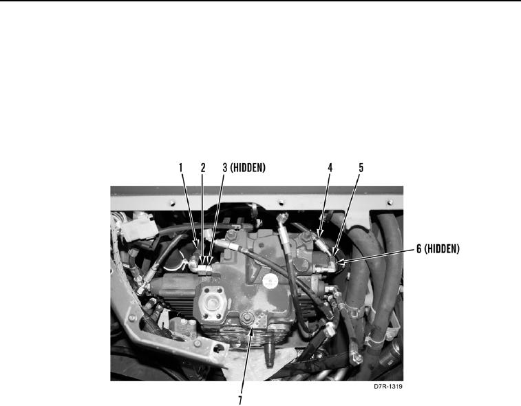
5. Loosen five tube nuts (Figure 3, Item 1) and remove five hoses (Figure 3, Item 2) and O-rings (Figure 3, Item 3)
from front side of control valve (Figure 3, Item 7). Discard O-rings and set hoses aside.
6. Loosen six tube nuts (Figure 3, Item 5) and remove six hoses (Figure 3, Item 4) and O-rings (Figure 3, Item 6)
from rear side of control valve (Figure 3, Item 7). Discard O-rings and set hoses aside.
Figure 3. Hoses and Lines.
0211