
TM 5-2410-241-23-3
0211
REMOVAL CONTINUED
N OT E
Care must be taken to ensure that fluids ae contained during performance of inspection,
r
maintenance, testing, adjusting and repair of the product. Be prepared to collect the fluid
with suitable containers before opening any compartment or disassembling any
component containing fluids.
Dispose of all fluids accordingto local regulations and mandates.
Perform disassembly on a clean surface.
Clean exterior of component to prevent contamination.
Plug all lines, hoses and tubes to prevent contamination and leaks.
Tag and mark all hoses and lines to aid installation.
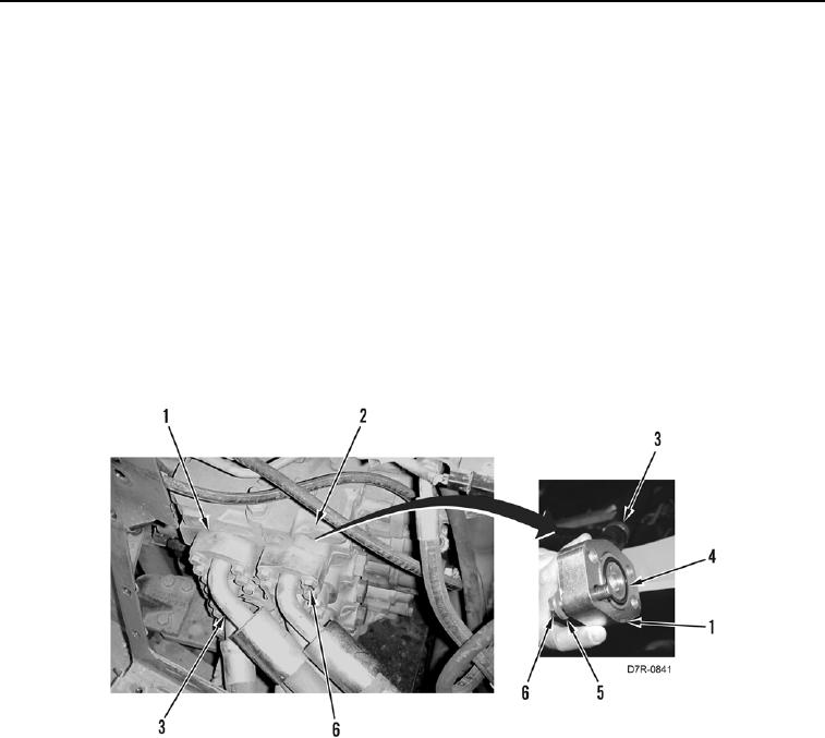
3. Remove 40 bolts (Figure 2, Item 6), washers (Figure 2, Item 5), 10 flanges (Figure 2, Item 1), and 10 hoses
(Figure 2, Item 3) from control valve (Figure 2, Item 2).
4. Remove 10 O-rings (Figure 2, Item 4) from hoses (Figure 2, Item 3). Discard O-rings.
Figure 2. Control Valve Hoses.
0211