TM 5-2410-241-23-3
0211
REMOVAL CONTINUED
N OT E
Note orientation and location of steering control to aid installation.
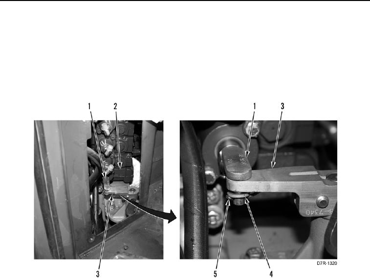
7. Remove two cotter pins (Figure 4, Item 5) and washers (Figure 4, Item 4) from linkage (Figure 4, Item 1).
Discard cotter pins.
8. Remove linkage (Figure 4, Item 1) from control valve (Figure 4, Item 2) and lever (Figure 4, Item 3).
Figure 4. Control Lever Linkage.
0211

