
TM 5-2410-241-23-3
0220
CLEANING AND INSPECTION
000220
1. Clean all parts IAW Mechanical General Maintenance Instructions (WP 0295).
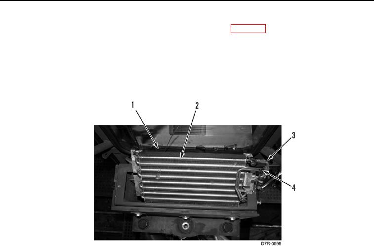
2. Inspect evaporator coil (Figure 5, Item 1) for cracks, damage, or coolant leakage. Replace evaporator coil.
3. Inspect evaporator coil (Figure 5, Item 1) for bent fins (Figure 5, Item 2). Bent fins may be gently straightened
by use of a small screwdriver.
4. Inspect pipe (Figure 5, Item 3) and outlet pipe (Figure 5, Item 4) for cracks, breaks, broken welds, coolant
leakage or deformity. Replace evaporator coil.
Figure 5. A/C Evaporator Inspection.
0220
END OF TASK
INSTALLATION
000220
1. Install evaporator coil (Figure 4, Item 8) on platform (Figure 4, Item 7).
N OT E
Coat new O-rings with clean refrigerant oil before installation.
Install hoses as tagged during removal.
2. Install new O-ring (Figure 4, Item 4) on hose assembly (Figure 4, Item 3).
3. Connect hose assembly (Figure 4, Item 3) on evaporator coil (Figure 4, Item 8).
4. Install new O-ring (Figure 4, Item 2) to hose assembly (Figure 4, Item 1).
5. Connect hose assembly (Figure 4, Item 1) on evaporator coil (Figure 4, Item 8).
6. Install two washers (Figure 4, Item 5) and bolts (Figure 4, Item 6) on evaporator coil (Figure 4, Item 8).