
TM 5-2410-241-23-3
0251
CLEANING AND INSPECTION
000251
Clean and inspect all parts IAW Mechanical General Maintenance Instructions (WP 0295).
END OF TASK
INSTALLATION
000251
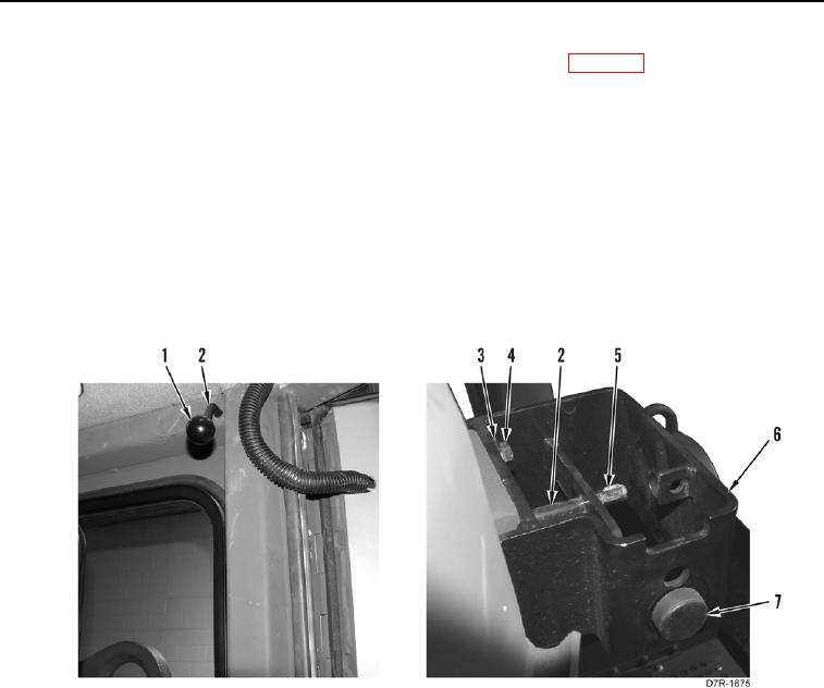
1. Install new rubber washer seal (Figure 4, Item 1) on cab.
2. Install bracket (Figure 5, Item 6), four washers (Figure 5, Item 3), and bolts (Figure 5, Item 4) on cab.
3. Install bumper (Figure 5, Item 7) on bracket (Figure 5, Item 6).
4. Install handle (Figure 5, Item 1) on shaft (Figure 5, Item 2).
5. Install shaft (Figure 5, Item 2) on bracket (Figure 5, Item 6) and cab.
6. Install key (Figure 5, Item 5) on shaft (Figure 5, Item 2).
Figure 5. Latch Assembly.
0251