
TM 5-2410-241-23-3
0251
INSTALLATION CONTINUED
N OT E
Position nut and bolt as noted during removal.
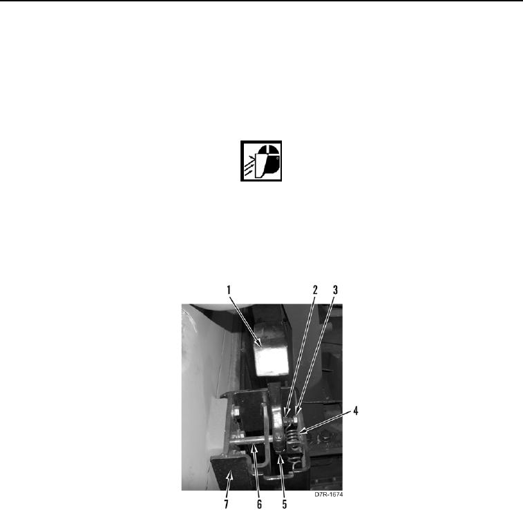
7. Install door striker (Figure 6, Item 1) on shaft (Figure 6, Item 6) and bracket (Figure 6, Item 7).
8. Loosen bolt (Figure 6, Item 3) and tighten nut (Figure 6, Item 2) on door striker (Figure 6, Item 1).
WARN I N G
Springs may have significant spring tension, depending upon type or position of spring.
Use extreme caution when installing springs. Springs under tension can act as projectiles
when released and could result in severe injury to personnel.
9. Install spring (Figure 6, Item 4) on bolt (Figure 6, Item 3) and bracket (Figure 6, Item 7).
10. Install bolt (Figure 6, Item 5) on door striker (Figure 6, Item 1).
Figure 6. Latch Striker.
0251