Home
Download PDF
Order CD-ROM
Order in Print
Figure 16. Upper Half of Instrument Panel.
Figure 18. Connector Clamps and Brackets.
Field Maintenance Manual 3 D7R Dozer Type I With Winch and Type II With Ripper
Page Navigation
722
723
724
725
726
727
728
729
730
731
732
TM
5-2410-241-23-3
0262
ASSEMBLY
CONTINUED
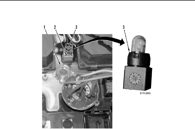
16.
Install
indicator
bulb
(
Figure
17,
Item
3) on
holder
(
Figure
17,
Item
2)
and
instrument
panel
(
Figure
17,
Item
1).
Figure
17.
Indicator
Bulb.
0262
0262-16