• Home
  • Download PDF
  • Order CD-ROM
  • Order in Print
Figure 20. Support Cable and Gauge Lights.
Figure 23. Back of Instrument Panel.

Field Maintenance Manual 3 D7R Dozer Type I With Winch and Type II With Ripper
Page Navigation
  726    727    728    729    730  731  732    733    734    735    736  
img
.
TM 5-2410-241-23-3
0262
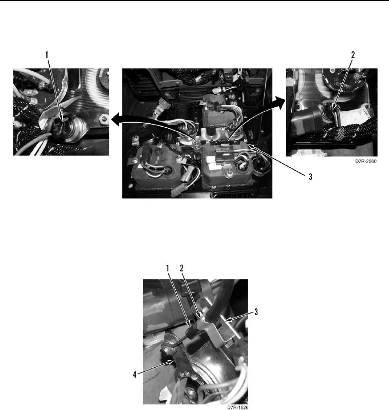
INSTALLATION CONTINUED
4. Install two lights (Figure 21, Items 1 and 2) on instrument panel (Figure 21, Item 3).
Figure 21. Instrument Panel Lights.
0262
5. Install cable (Figure 22, Item 1) on heater control valve (Figure 22, Item 4).
6. Install clip (Figure 22, Item 2) on cable (Figure 22, Item 1) and bracket (Figure 22, Item 3).
Figure 22. Heater Control Cable.
0262
0262-20


Privacy Statement
Press Release
Contact

© Copyright Integrated Publishing, Inc.. All Rights Reserved.