
TM 5-2410-241-23-3
0262
INSTALLATION CONTINUED
N OT E
Install electrical connectors as tagged during removal.
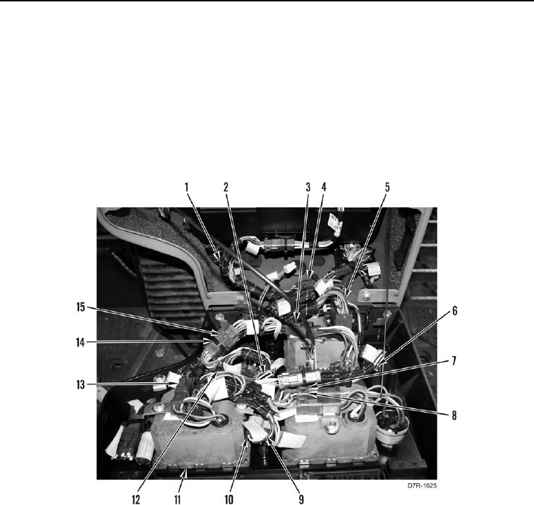
7. Connect four plugs (Figure 23, Items 2, 5, 6, and 12) on instrument panel (Figure 23, Item 11).
8. Connect eight electrical connectors (Figure 23, Items 3, 4, 7, 8, 9, 10, 13, and 15) on instrument panel
(Figure 23, Item 11).
9. Install new tiedown straps (Figure 23, Item 14) to secure wiring harness (Figure 23, Item 1) to instrument panel
(Figure 23, Item 11).
Figure 23. Back of Instrument Panel.
0262