• Home
  • Download PDF
  • Order CD-ROM
  • Order in Print
Figure 18. Connector Clamps and Brackets.
Figure 20. Support Cable and Gauge Lights.

Field Maintenance Manual 3 D7R Dozer Type I With Winch and Type II With Ripper
Page Navigation
  724    725    726    727    728  729  730    731    732    733    734  
img
.
TM 5-2410-241-23-3
0262
ASSEMBLY CONTINUED
N OT E
Position spacer as noted during removal.
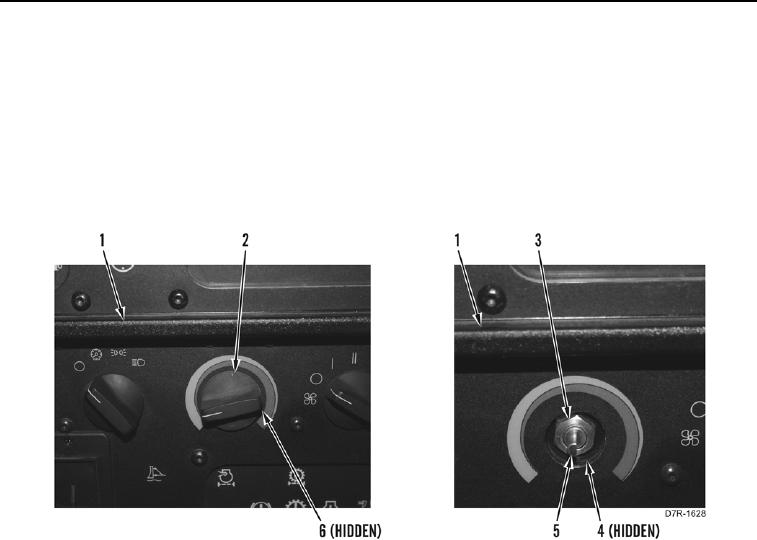
21. Install spacer (Figure 19, Item 4), heater control (Figure 19, Item 5), and nut (Figure 19, Item 3) on instrument
panel (Figure 19, Item 1).
22. Install heater control knob (Figure 19, Item 2) and tighten setscrew (Figure 19, Item 6) on instrument panel
(Figure 19, Item 1).
Figure 19. Heater Control Knob.
0262
END OF TASK
0262-18


Privacy Statement
Press Release
Contact

© Copyright Integrated Publishing, Inc.. All Rights Reserved.