
TM 5-2410-241-23-3
0278
REMOVAL
000278
WARN I N G
Contact with oil can damage skin. Wear gloves when handling oil. If oil contacts skin, wash
it off immediately.
Lubricating oil is very slippery. Immediately wipe up any spills.
Failure to follow these warningsmay cause injury to personnel.
C AU T I O N
Cap and plug all hydraulic hose ends to prevent leaks and contamination. Failure to follow
this caution may result in damage to equipment.
N OT E
Collect fluid in suitable containers.
Dispose of all fluids accordingto local regulations and mandates.
This procedure is for one ripper tilt cylinde. Use the same procedure for other ripper tilt
r
cylinder.
Tag and identify hoses to aid installation.
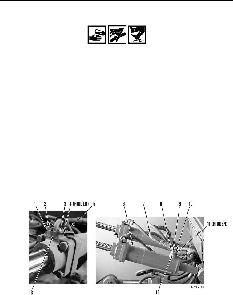
1. Remove four bolts (Figure 1, Item 2), washers (Figure 1, Item 1), plate (Figure 1, Item 3), flange (Figure 1,
Item 13), and hose (Figure 1, Item 5) from rod end of ripper tilt cylinder (Figure 1, Item 6). Set hose aside.
2. Remove O-ring (Figure 1, Item 4) from hose (Figure 1, Item 5). Discard O-ring.
3. Remove four bolts (Figure 1, Item 8), washers (Figure 1, Item 9), plate (Figure 1, Item 10), flange
(Figure 1, Item 12), and hose (Figure 1, Item 7) from head end of ripper tilt cylinder (Figure 1, Item 6). Set hose
aside.
4. Remove O-ring (Figure 1, Item 11) from hose (Figure 1, Item 7). Discard O-ring.
Figure 1. Ripper Tilt Cylinder Hose Assemblies.
0278