
TM 5-2410-241-23-3
0278
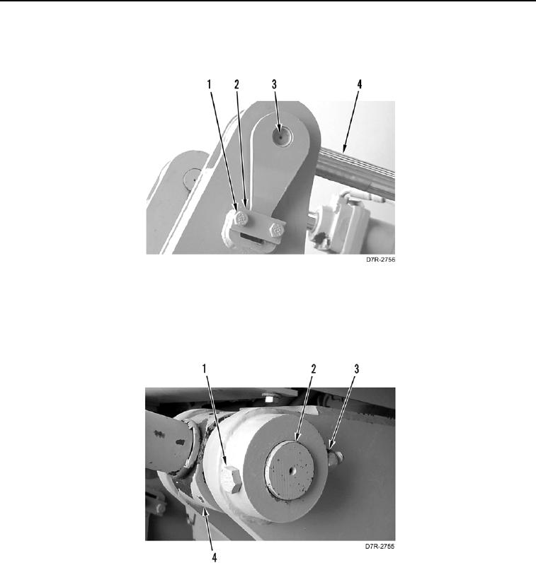
INSTALLATION CONTINUED
3. Install pin assembly (Figure 6, Item 3), plate (Figure 6, Item 2), and two bolts (Figure 6, Item 1) on rod end of
ripper tilt cylinder (Figure 6, Item 4).
Figure 6. Ripper Tilt Cylinder Rod End.
0278
4. Install pin (Figure 7, Item 2), bolt (Figure 7, Item 1), and new locknut (Figure 7, Item 3) on head end of ripper tilt
cylinder (Figure 7, Item 4).
5. Remove lifting device from ripper tilt cylinder (Figure 7, Item 4).
Figure 7. Ripper Tilt Cylinder Head End.
0278