
TM 5-2410-241-23-3
0279
REMOVAL
000279
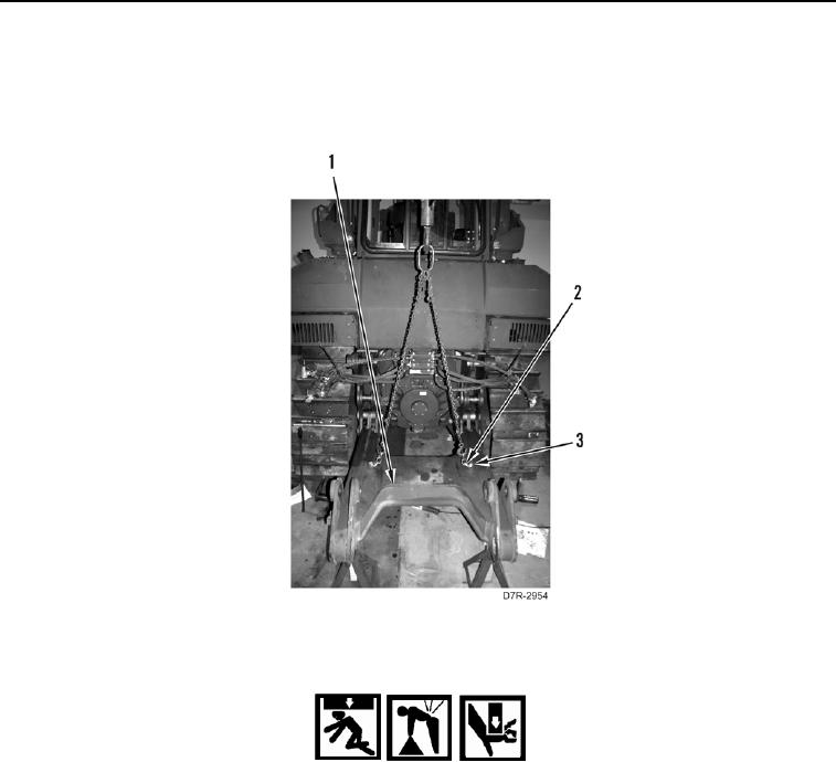
1. Install two lifting links (Figure 1, Item 2) and bolts (Figure 1, Item 3) on ripper frame (Figure 1, Item 1).
2. Attach suitable lifting device on ripper frame (Figure 1, Item 1).
3. Support ripper frame (Figure 1, Item 1) with suitable supports.
Figure 1. Ripper Frame Support.
0279
WARN I N G
Use extreme caution when handling heavy parts. Provide adequate support and use
assistance during procedure. Ensure lifting device used is in good condition and of
suitable load capacity. Keep clear of heavy parts supported only by lifting device. Failure to
follow this warning may cause injury or death to personnel.
N OT E
Ripper frame weighs approximately 1650 lb (750 kg).
N OT E
Note orientation of plates to aid installation.
Note location and quantity of shims to aid installation.
Loosen outside bolts prior to inside bolts.