
TM 5-2410-241-23-3
0279
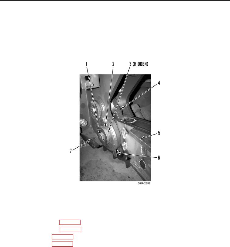
INSTALLATION CONTINUED
5. With assistance, install ripper frame (Figure 6, Item 5), shims (Figure 6, Item 6), lower pivot pin (Figure 6,
Item 3), two plates (Figure 6, Item 2), and two bolts (Figure 6, Item 1) on ripper mounting (Figure 6, Item 7) and
tiedown plate (Figure 6, Item 4).
6. Repeat step 5 for other side of ripper frame (Figure 6, Item 5).
7. Remove lifting device from ripper frame (Figure 6, Item 5).
8. Remove two bolts (Figure 5, Item 3) and lifting links (Figure 5, Item 2) from ripper frame (Figure 5, Item 1).
Figure 6. Ripper Frame.
0279
END OF TASK
FOLLOW-ON TASKS
000279
1. Install ripper lift cylinders (WP 0277).
2. Install ripper tilt cylinders (WP 0278).
3. Install ripper carriage (WP 0282).
4. Install bottom guards (WP 0199).
5. Verify correct operation of machine (TM 5-2410-241-10).
END OF TASK
END OF WORK PACKAGE