
TM 5-2410-241-23-3
0279
INSTALLATION
000279
C AU T I O N
Tiedown plates are installed with flat side facing toward front of machine.
Plates are installed with flat side toward pin, depression toward bolt.
Failure to follow this caution may result in damage to equipment.
N OT E
Install shims as noted.
Tighten inside bolts first.
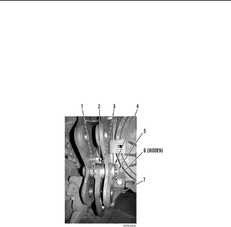
1. Install tiedown plate (Figure 4, Item 2), upper pivot pin (Figure 4, Item 6), shims (Figure 4, Item 1), two spacers
(Figure 4, Item 3), plates (Figure 4, Item 4), and bolts (Figure 4, Item 5) on ripper mounting (Figure 4, Item 7).
2. Repeat step 1 for other side of ripper mounting (Figure 4, Item 7).
Figure 4. Tiedown Plate.
0279