
TM 5-2410-241-23-3
0278
INSTALLATION CONTINUED
N OT E
Install hoses as tagged during removal.
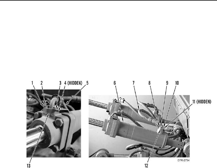
6. Install new O-ring (Figure 8, Item 11) on hose (Figure 8, Item 7).
7. Install hose (Figure 8, Item 7), flange (Figure 8, Item 12), plate (Figure 8, Item 10), four washers (Figure 8,
Item 9), and bolts (Figure 8, Item 8) on head end of ripper tilt cylinder (Figure 8, Item 6).
8. Install new O-ring (Figure 8, Item 4) on hose (Figure 8, Item 5).
9. Install hose (Figure 8, Item 5), flange (Figure 8, Item 13), plate (Figure 8, Item 3), four washers (Figure 8,
Item 1), and bolts (Figure 8, Item 2) on rod end of ripper tilt cylinder (Figure 8, Item 6).
Figure 8. Ripper Tilt Cylinder Assemblies.
0278
END OF TASK
FOLLOW-ON TASKS
000278
1. Fill hydraulic system with oil (WP 0184).
2. Verify correct operation of machine (TM 5-2410-241-10).
END OF TASK
END OF WORK PACKAGE