
TM 5-2410-240-23-1
0030
CHARGING SYSTEM TEST CONTINUED
00030
7. Remove ammeter from machine.
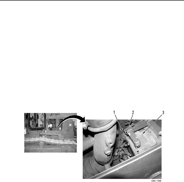
8. Position boot (Figure 3, Item 1) aside from B+ terminal (Figure 3, Item 2).
9. Place multimeter positive lead on B+ terminal (Figure 3, Item 2) of alternator (Figure 3, Item 3).
10. Place multimeter negative lead on alternator (Figure 3, Item 3).
11. With engine still running, have an assistant monitor digital multimeter. Voltage reading should be 24-28 Volts.
a. If voltage is within specified range, alternator and charging system are OK.
b. If voltage is less than 24-Volts or more than 28-Volts, then alternator is faulty. Replace alternator
(WP 0090).
12. Position boot (Figure 3, Item 1) over B+ terminal (Figure 3, Item 2).
N OT E
Turn off front and rear work lights, headlights, cab fan, and dome light (TM 5-2410-240-
10).
13. Shut down engine (TM-5-2410-240-10).
14. Turn battery disconnect switch to OFF position (TM-5-2410-240-10).
15. Install right engine access door (WP 0186).
Figure 3. Alternator.
0030
END OF TASK