
TM 5-2410-240-23-2
0040
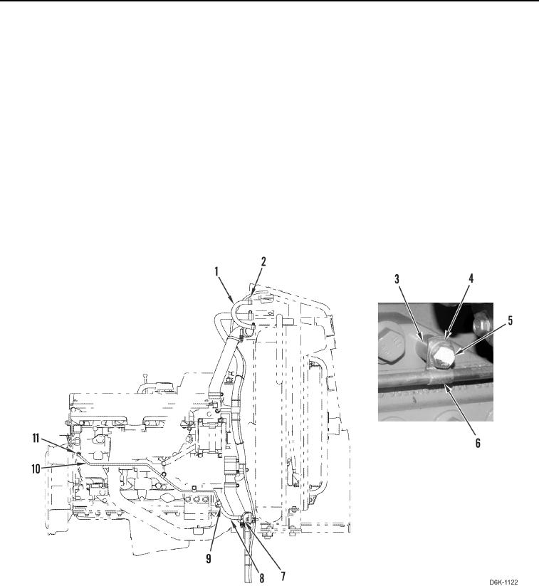
COOLING SYSTEM TUBE AND HOSES REMOVAL CONTINUED
N OT E
Tag and mark hoses and tube to aid installation.
Note hose and tube routing to aid installation.
Cap hose and tube ends and plug fittings.
3. Loosen two clamps (Figure 4, Item 2) and remove hose (Figure 4, Item 1) from machine.
4. Remove two clamps (Figure 4, Item 2) from hose (Figure 4, Item 1).
5. Loosen two clamps (Figure 4, Item 9) and remove hose (Figure 4, Item 8) from tube (Figure 4, Item 10) and
drain (Figure 4, Item 7).
6. Remove two clamps (Figure 4, Item 9) from hose (Figure 4, Item 8).
7. Loosen fitting (Figure 4, Item 11), remove two bolts (Figure 4, Item 5), washers (Figure 4, Item 4), clamps
(Figure 4, Item 6), tube (Figure 4, Item 10), and spacers (Figure 4, Item 3) from machine.
8. Remove two clamps (Figure 4, Item 6) from tube (Figure 4, Item 10).
Figure 4. Tube, Hoses, and Retaining Hardware.
0040
END OF TASK