• Home
  • Download PDF
  • Order CD-ROM
  • Order in Print
Figure 5. Tube, Hoses, and Retaining Hardware.
Figure 7. Cooling System Hoses and Retaining Hardware.

Field Maintenance Manual 2 D6K Dozer Type I With Winch and Type II With Ripper
Page Navigation
  54    55    56    57    58  59  60    61    62    63    64  
img
. .
TM 5-2410-240-23-2
0040
COOLING SYSTEM TUBE AND HOSES INSTALLATION CONTINUED
N OT E
Remove all caps and plugs prior to installation.
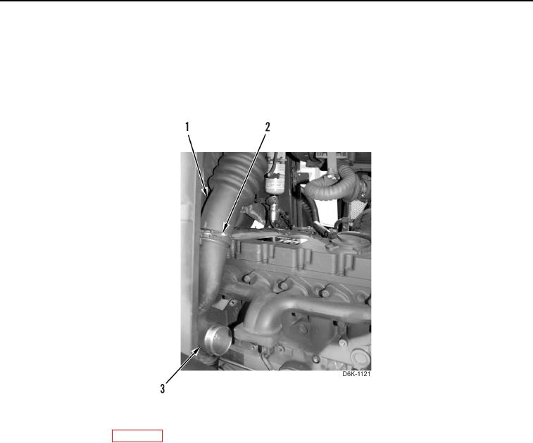
8. Install air inlet elbow (Figure 6, Item 3) on hose (Figure 6, Item 1) and tighten clamp (Figure 6, Item 2).
Figure 6. Air Inlet Elbow and Hose.
0040
9. Install turbocharger (WP 0079).
END OF TASK
0040-7


Privacy Statement
Press Release
Contact

© Copyright Integrated Publishing, Inc.. All Rights Reserved.