
TM 5-2410-240-23-2
0040
CLEANING AND INSPECTION
00040
Clean and inspect all parts IAW Mechanical General Maintenance Instructions (WP 0282).
END OF TASK
COOLING SYSTEM TUBE AND HOSES INSTALLATION
00040
N OT E
Remove all caps and plugs prior to installation and install hoses and tube as noted during
removal.
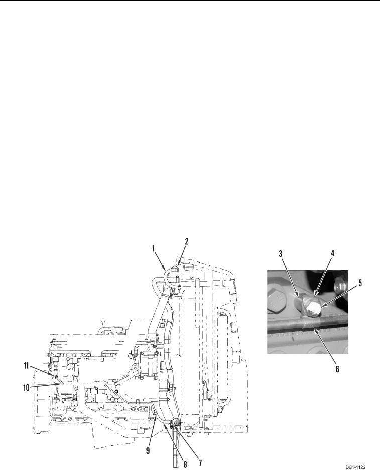
1. Install two clamps (Figure 5, Item 6) on tube (Figure 5, Item 10).
2. Install tube (Figure 5, Item 10), two spacers (Figure 5, Item 3), clamps (Figure 5, Item 6), washers (Figure 5,
Item 4), and bolts (Figure 5, Item 5) on machine.
3. Tighten fitting (Figure 5, Item 11).
4. Install two clamps (Figure 5, Item 9) on hose (Figure 5, Item 8).
5. Install hose (Figure 5, Item 8) on tube (Figure 5, Item 10) and drain (Figure 5, Item 7) and tighten two clamps
(Figure 5, Item 9).
6. Install two clamps (Figure 5, Item 2) on hose (Figure 5, Item 1).
7. Install hose (Figure 5, Item 1) on machine and tighten two clamps (Figure 5, Item 2).
Figure 5. Tube, Hoses, and Retaining Hardware.
0040