
TM 5-2410-240-23-2
0047
CLEANING AND INSPECTION
00047
Clean and inspect all parts IAW Mechanical General Maintenance Instructions (WP 0282).
END OF TASK
INSTALLATION
00047
N OT E
Route cables and install electrical connectors as noted during removal.
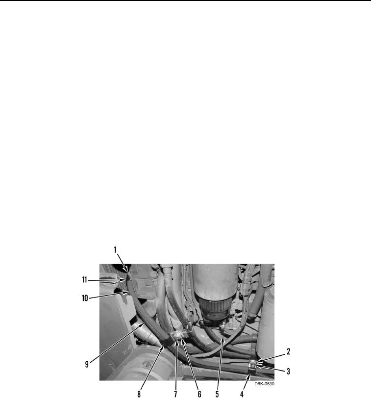
1. Position negative cable (Figure 5, Item 9) and positive cable (Figure 5, Item 10) on engine.
2. Install clamp (Figure 5, Item 11) on negative cable (Figure 5, Item 9) and positive cable (Figure 5, Item 10).
3. Install clamp (Figure 5, Item 11) and bolt (Figure 5, Item 1) on engine (Figure 5, Item 5). Hand tighten bolt.
4. Install clamp (Figure 5, Item 8) on negative cable (Figure 5, Item 9) and positive cable (Figure 5, Item 10).
5. Install clamp (Figure 5, Item 8), washer (Figure 5, Item 6), and bolt (Figure 5, Item 7) on engine (Figure 5,
Item 5). Hand tighten bolt.
6. Install clamp (Figure 5, Item 4) on negative cable (Figure 5, Item 9) and positive cable (Figure 5, Item 10).
7. Install clamp (Figure 5, Item 4), washer (Figure 5, Item 2), and nut (Figure 5, Item 3) on engine (Figure 5,
Item 5). Hand tighten nut.
8. Torque bolt (Figure 5, Item 1), bolt (Figure 5, Item 7), and nut (Figure 5, Item 3) to 16 lb-ft (22 Nm) on engine
(Figure 5, Item 5).
Figure 5. NATO Slave Cables and Brackets.
0047