
TM 5-2410-240-23-2
0088
REMOVAL CONTINUED
N OT E
Note location of tiedown straps and harness routing to aid installation.
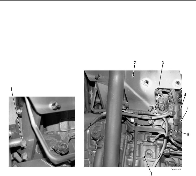
7. Release two fuel tubes (Figure 4, Item 3) from three clips (Figure 4, Item 6) on plate (Figure 4, Item 2).
8. Remove four bolts (Figure 4, Item 1) and plate (Figure 4, Item 2) from engine (Figure 4, Item 7).
9. Remove four tiedown straps (Figure 4, Item 5) from harness (Figure 4, Item 4) and position harness aside.
Discard tiedown straps.
Figure 4. Fuel Tubes, Harness, and Retaining Hardware.
0088