
TM 5-2410-240-23-2
0088
INSTALLATION CONTINUED
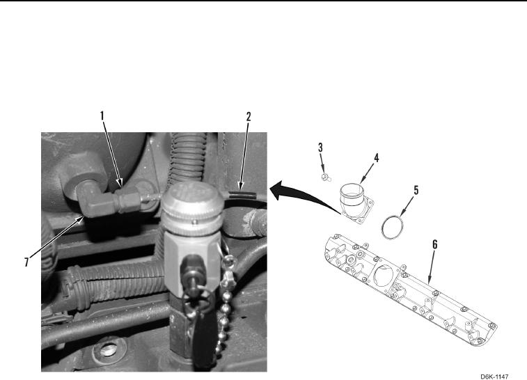
5. Install new O-ring (Figure 7, Item 5), inlet connection (Figure 7, Item 4), and four bolts (Figure 7, Item 3) on
inlet manifold (Figure 7, Item 6). Torque bolts to 16 lb-ft (22 Nm).
6. Install fitting (Figure 7, Item 7) on inlet connection (Figure 7, Item 4).
7. Install ether injection tube (Figure 7, Item 2) on fitting (Figure 7, Item 7) and tighten nut (Figure 7, Item 1).
Figure 7. Ether Injection Tube Hardware and Inlet Manifold Components.
0088