
TM 5-2410-240-23-2
0088
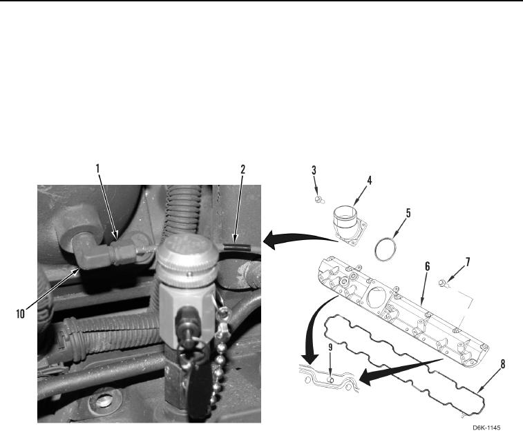
REMOVAL CONTINUED
10. Loosen nut (Figure 5, Item 1) and remove ether injection tube (Figure 5, Item 2) from fitting (Figure 5, Item 10).
11. Remove fitting (Figure 5, Item 10) from inlet connection (Figure 5, Item 4).
12. Remove four bolts (Figure 5, Item 3), inlet connection (Figure 5, Item 4), and O-ring (Figure 5, Item 5) from
inlet manifold (Figure 5, Item 6). Discard O-ring.
13. Remove 15 bolts (Figure 5, Item 7) and inlet manifold (Figure 5, Item 6) from engine.
14. Remove gasket (Figure 5, Item 8) from inlet manifold (Figure 5, Item 6). Discard gasket.
15. Remove two dowel pins (Figure 5, Item 9) from inlet manifold (Figure 5, Item 6). Discard dowel pins.
Figure 5. Ether Injection Tube Hardware and Inlet Manifold Components.
0088
END OF TASK
CLEANING AND INSPECTION
00088
Clean and inspect all components IAW Mechanical General Maintenance Instructions (WP 0282).
END OF TASK