
TM 5-2410-240-23-2
0088
INSTALLATION CONTINUED
N OT E
Route harness and install tiedown straps as noted during removal.
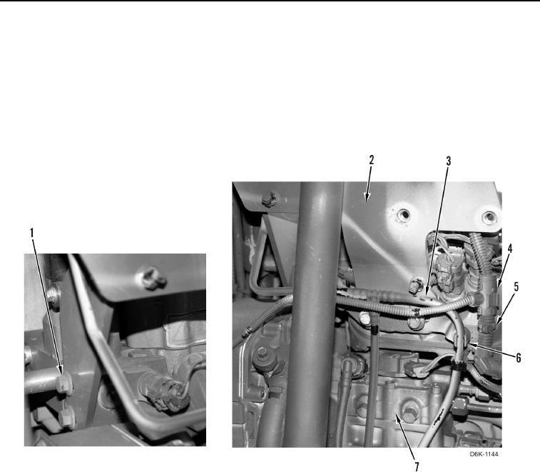
8. Install plate (Figure 8, Item 2) and four bolts (Figure 8, Item 1) on engine (Figure 8, Item 7).
9. Install two fuel tubes (Figure 8, Item 3) on three clips (Figure 8, Item 6) on plate (Figure 8, Item 2).
10. Position harness (Figure 8, Item 4) and install four new tiedown straps (Figure 8, Item 5).
Figure 8. Fuel Tubes, Harness, and Retaining Hardware.
0088