
TM 5-2410-240-23-2
0103
INSTALLATION
000103
N OT E
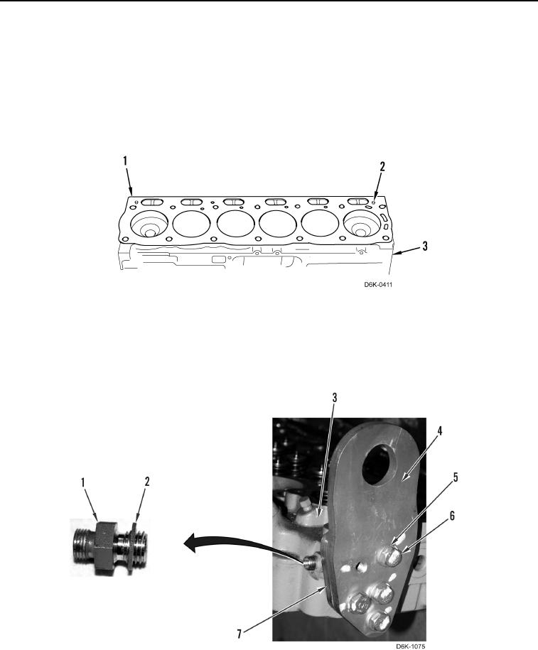
Install dowel pins in proper location in cylinder block as noted during removal.
1. Install two new dowel pins (Figure 12, Item 2) on cylinder block (Figure 12, Item 3).
2. Align new cylinder head gasket (Figure 12, Item 1) with dowel pins (Figure 12, Item 2) on cylinder block
(Figure 12, Item 3).
Figure 12. Cylinder Head Guide Bolts.
0103
3. Install spacer plate (Figure 13, Item 7), lifting bracket (Figure 13, Item 4), four washers (Figure 13, Item 5), and
bolts (Figure 13, Item 6) on cylinder head (Figure 13, Item 3).
4. Install new washer (Figure 13, Item 2) and connector (Figure 13, Item 1) on cylinder head (Figure 13, Item 3).
Figure 13. Connector and Lifting Plate.
0103