
TM 5-2410-240-23-2
0103
INSTALLATION CONTINUED
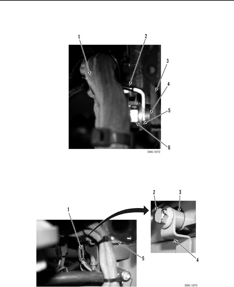
18. Position wiring harness (Figure 19, Item 1), spacer (Figure 19, Item 4), bracket (Figure 19, Item 2), washer
(Figure 19, Item 5), and bolt (Figure 19, Item 6) on right rear of cylinder head (Figure 19, Item 3).
Figure 19. Harness - Right Rear of Cylinder Head.
0103
19. Position wastegate tubes (Figure 20, Item 1), spacer (Figure 20, Item 3), clamp (Figure 20, Item 4), and bolt
(Figure 20, Item 2) on rear of cylinder head (Figure 20, Item 5).
Figure 20. Right Rear of Cylinder Head.
0103