
TM 5-2410-240-23-2
0104
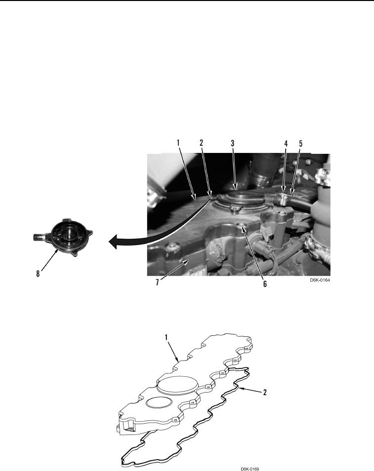
REMOVAL
000104
Valve Mechanism Cover Removal
000104
1. Loosen clamp (Figure 1, Item 4) and disconnect breather hose (Figure 1, Item 5) from breather (Figure 1,
Item 3).
N OT E
Note position and length of bolts to aid installation.
2. Remove 15 bolts (Figure 1, Item 6) and valve cover (Figure 1, Item 1) from base (Figure 1, Item 7).
3. Remove four screws (Figure 1, Item 2), breather (Figure 1, Item 3), and O-ring (Figure 1, Item 8) from valve
cover (Figure 1, Item 1). Discard O-ring.
Figure 1. Valve Cover.
0104
4. Remove gasket (Figure 2, Item 2) from valve cover (Figure 2, Item 1). Discard gasket.
Figure 2. Valve Cover Gasket.
0104