
TM 5-2410-240-23-2
0104
REMOVAL CONTINUED
000104
N OT E
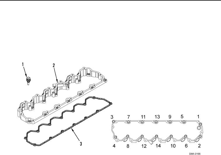
Loosen bolts in sequence to prevent distortion of valve cover base.
4. Remove 14 valve cover base bolts (Figure 4, Item 1) from valve cover base (Figure 4, Item 2) in sequence
shown (Figure 4).
5. Remove valve cover base (Figure 4, Item 2) and gasket (Figure 4, Item 3) from machine. Discard gasket.
Figure 4. Valve Cover Base.
0104
END OF TASK
CLEANING AND INSPECTION
000104
Clean and inspect all components IAW Mechanical General Maintenance Instructions (WP 0282).
END OF TASK
INSTALLATION
000104
Valve Cover Base Installation
000104
N OT E
Ensure gasket is seated correctly in groove in machined face of valve cover base.
1. Install new gasket (Figure 4, Item 3) on valve cover base (Figure 4, Item 2).
2. Install 14 bolts (Figure 4, Item 1) and valve cover base (Figure 4, Item 2) on machine. Tighten bolts in
sequence shown (Figure 4) to 79 lb-in. (9 Nm).