
TM 5-2410-240-23-2
0104
INSTALLATION CONTINUED
000104
N OT E
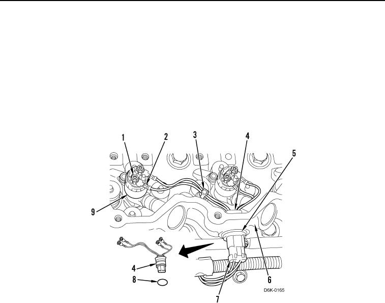
Install wires and wiring harness and tiedown straps as tagged and noted during removal.
3. Lubricate and install three new O-rings (Figure 5, Item 8), harness (Figure 5, Item 4), and circlips (Figure 5,
Item 5) on valve cover base (Figure 5, Item 6).
4. Connect three plugs (Figure 5, Item 7) to harness (Figure 5, Item 4).
5. Install 12 harness connections (Figure 5, Item 2) and nuts (Figure 5, Item 1) on six fuel injectors (Figure 5,
Item 9). Secure harness with three new tiedown straps (Figure 5, Item 3).
Figure 5. Fuel Injector Harness.
0104
END OF TASK