
TM 5-2410-240-23-2
0104
REMOVAL CONTINUED
Valve Cover Base Removal
000104
N OT E
Tag wires and wiring harness to aid installation.
Note routing of harness and position of tiedown straps to aid installation.
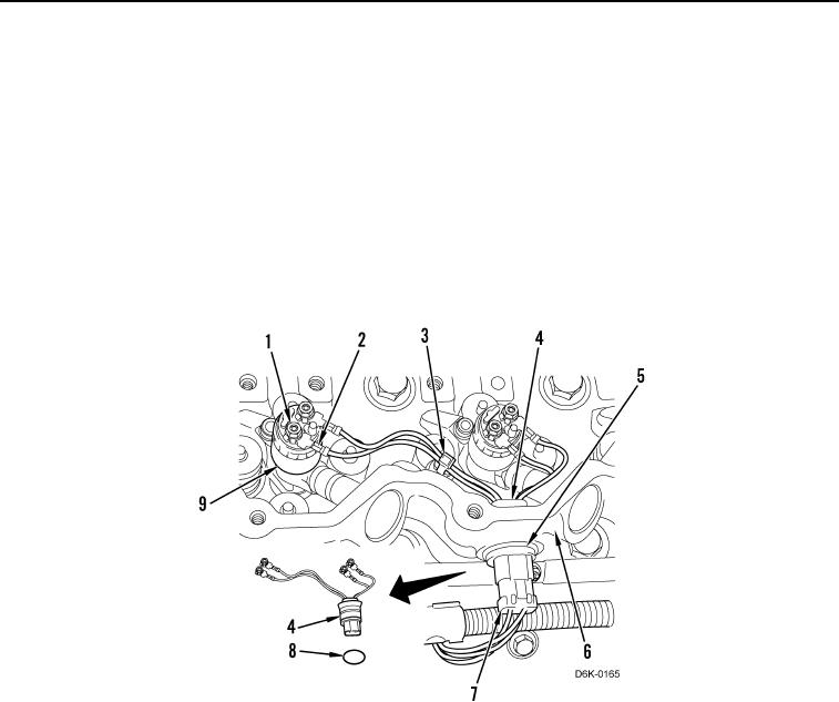
1. Remove 12 nuts (Figure 3, Item 1) and harness connections (Figure 3, Item 2) from six fuel injectors (Figure 3,
Item 9). Remove and discard three tiedown straps (Figure 3, Item 3).
2. Disconnect three plugs (Figure 3, Item 7) from harness connectors (Figure 3, Item 4).
3. Remove three circlips (Figure 3, Item 5) and push three harness connectors (Figure 3, Item 4) and O-ring
(Figure 3, Item 8) inward to remove from valve cover base (Figure 3, Item 6). Discard O-ring.
Figure 3. Fuel Injector Harness.
0104