• Home
  • Download PDF
  • Order CD-ROM
  • Order in Print
Figure 21. Left Rear of Cylinder Head.
CYLINDER HEAD REPLACEMENT - Continued

Field Maintenance Manual 2 D6K Dozer Type I With Winch and Type II With Ripper
Page Navigation
  536    537    538    539    540  541  542    543    544    545    546  
img
.
TM 5-2410-240-23-2
0103
INSTALLATION CONTINUED
N OT E
Install wires as tagged at removal.
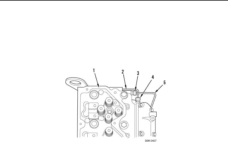
21. Install wastegate tube assembly (Figure 22, Item 2) and two tube nuts (Figure 22, Item 4) on cylinder head,
(Figure 22, Item 1).
22. Install transfer pump tube assembly (Figure 22, Item 5) and two tube nuts (Figure 22, Item 3) on cylinder head
(Figure 22, Item 1).
Figure 22. Fuel Lines.
0103
END OF TASK
0103-17


Privacy Statement
Press Release
Contact

© Copyright Integrated Publishing, Inc.. All Rights Reserved.