
TM 5-2410-240-23-2
0124
REMOVAL
000124
N OT E
Tag and mark hoses, lines, and fittings to aid installation.
Cap or plug hoses, lines, and fittings.
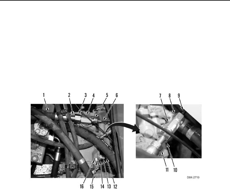
1. Loosen tube nut (Figure 1, Item 3) and disconnect hose (Figure 1, Item 1) from fitting (Figure 1, Item 4).
2. Loosen tube nut (Figure 1, Item 5) and disconnect line (Figure 1, Item 6) from fitting (Figure 1, Item 4).
3. Loosen tube nut (Figure 1, Item 8) and disconnect line (Figure 1, Item 9) from fitting (Figure 1, Item 7).
4. Loosen tube nut (Figure 1, Item 10) and disconnect hose (Figure 1, Item 11) from fitting (Figure 1, Item 7).
5. Loosen tube nut (Figure 1, Item 13) and disconnect hose (Figure 1, Item 12) from fitting (Figure 1, Item 14).
6. Remove two bolts (Figure 1, Item 16) and washers (Figure 1, Item 15) from implement pump (Figure 1, Item 2).
Figure 1. Hoses and Lines on Implement Pump.
0124