
TM 5-2410-240-23-2
0124
REMOVAL CONTINUED
N OT E
Tag and mark hoses and fittings to aid installation.
Use a container to catch any fluid that may drain from hoses, lines, or system. Dispose of
fluid IAW local policy and ordinances. Ensure all spills are cleaned up.
Cap or plug hoses and fittings.
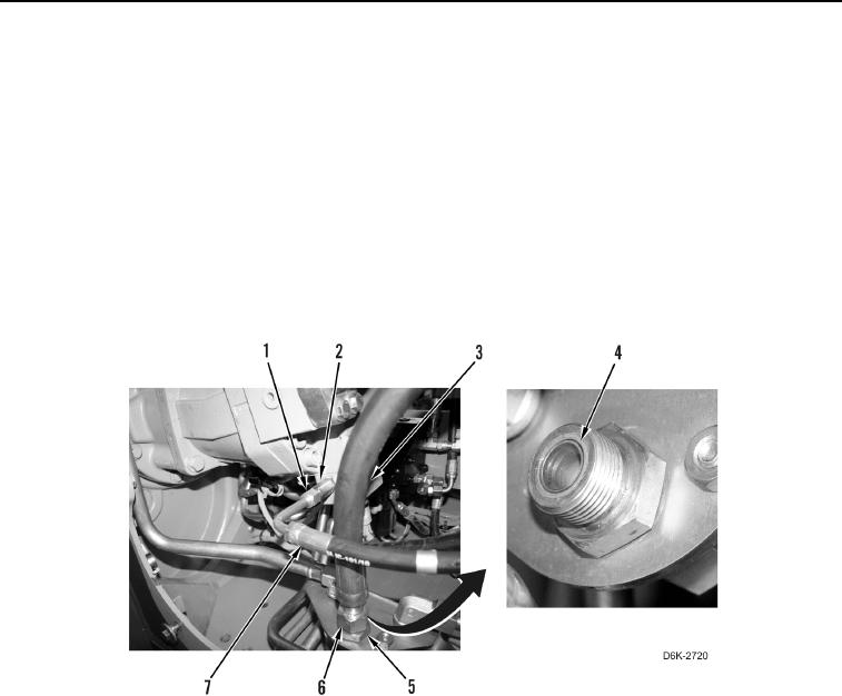
7. Loosen tube nut (Figure 2, Item 1) and disconnect hose (Figure 2, Item 7) from fitting (Figure 2, Item 2).
Position hose aside.
8. Loosen tube nut (Figure 2, Item 6) and disconnect hose (Figure 2, Item 3) from fitting (Figure 2, Item 5).
Position hose aside.
9. Remove two O-rings (Figure 2, Item 4) from fittings (Figure 2, Items 2 and 5). Discard O-rings.
Figure 2. Hoses on Right Hydrostatic Drive Motor and Bracket.
0124