
TM 5-2410-240-23-2
0124
REMOVAL CONTINUED
N OT E
Tag and mark hoses and fittings to aid installation.
Use a container to catch any fluid that may drain from hoses, lines, or system. Dispose of
fluid IAW local policy and ordinances. Ensure all spills are cleaned up.
Cap or plug hoses, fittings, and open ports.
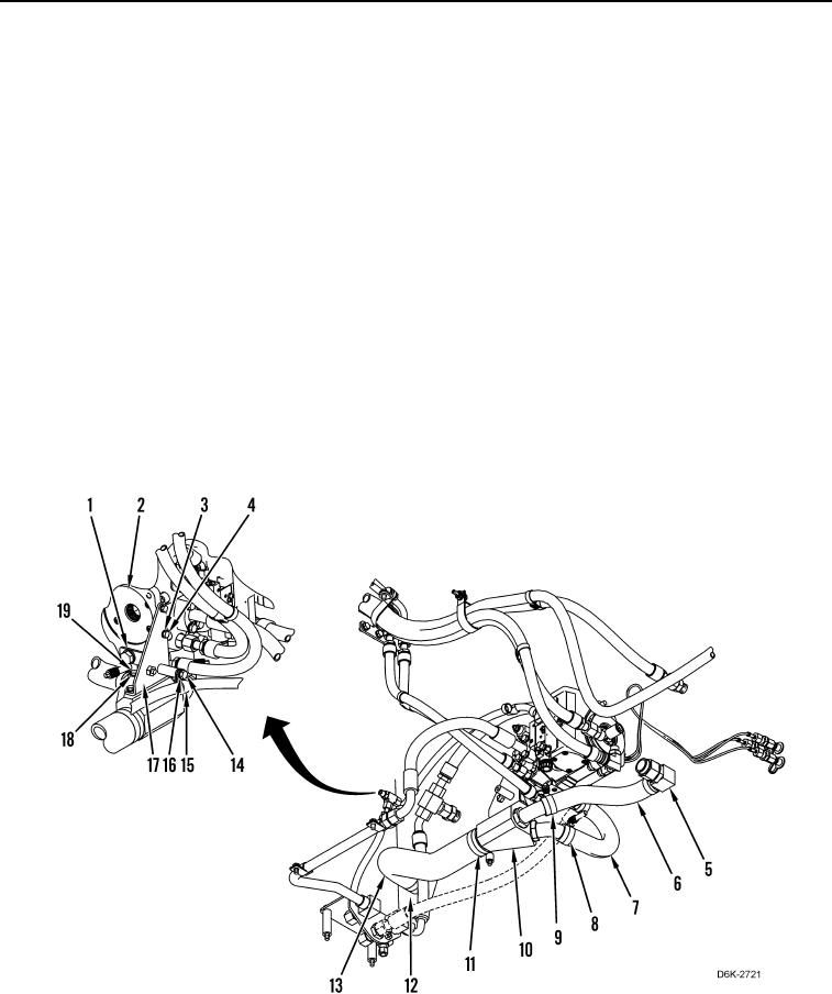
10. Loosen two clamps (Figure 3, Item 11) and disconnect hose (Figure 3, Item 13) from hydraulic tank (Figure 3,
Item 12) and manifold (Figure 3, Item 10) and remove hose from machine.
11. Loosen two clamps (Figure 3, Item 8) and disconnect hose (Figure 3, Item 7) from manifold (Figure 3, Item 10)
and winch piston pump (Figure 3, Item 2) and remove hose from machine.
12. Loosen two clamps (Figure 3, Item 9) and disconnect hose (Figure 3, Item 6) from fitting (Figure 3, Item 5) and
manifold (Figure 3, Item 10) and remove hose from machine.
13. Remove bolt (Figure 3, Item 14), washer (Figure 3, Item 16), and hose clamp (Figure 3, Item 15) from bracket
(Figure 3, Item 17).
14. Remove three bolts (Figure 3, Item 19), washers (Figure 3, Item 18), and manifold (Figure 3, Item 10) from
bracket (Figure 3, Item 17).
15. Remove three bolts (Figure 3, Item 4), washers (Figure 3, Item 3), and two brackets (Figure 3, Items 17 and 1)
from winch piston pump (Figure 3, Item 2).
Figure 3. Hoses, Bracket, Manifold, Winch Piston Pump, and Retaining Hardware.
0124