
TM 5-2410-240-23-2
0135
INSTALLATION CONTINUED
N OT E
Install hoses as noted during removal.
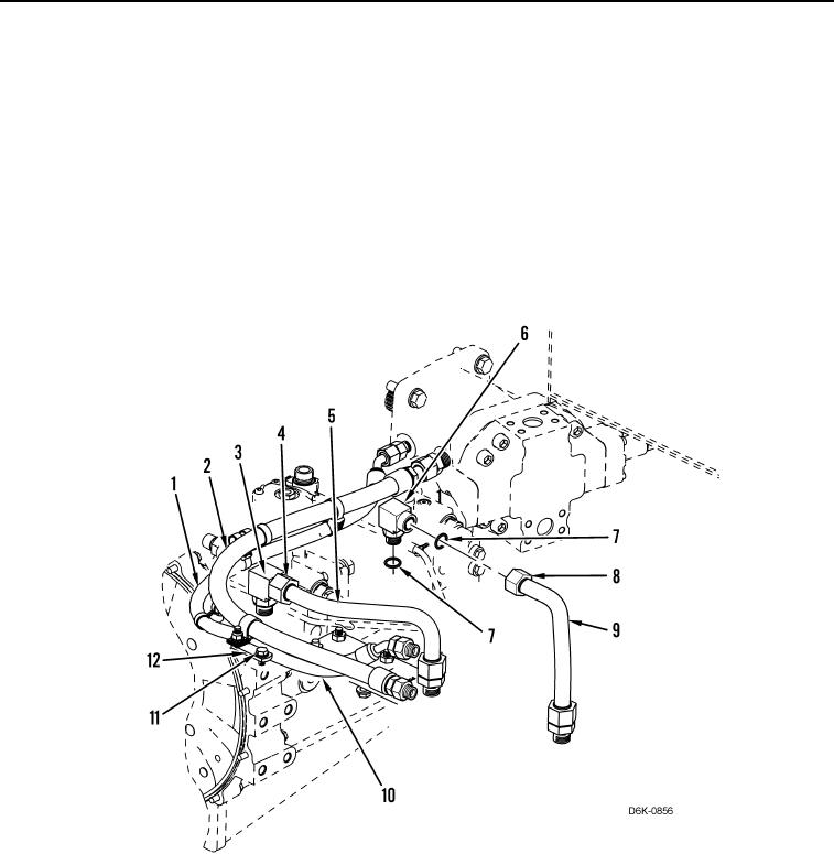
19. Install four new O-rings (Figure 15, Item 7) on two fittings (Figure 15, Items 3 and 6).
20. Install fittings (Figure 15, Item 3 and 6) on pump (Figure 15, Item 10).
21. Install line (Figure 15, Item 9) and tube nut (Figure 15, Item 8) on fitting (Figure 15, Item 6).
22. Install line (Figure 15, Item 5) and tube nut (Figure 15, Item 4) on fitting (Figure 15, Item 4).
23. Position hose (Figure 15, Item 2), and hose (Figure 15, Item 1) under pump (Figure 15, Item 10).
24. Install bolt (Figure 15, Item 11) on bracket (Figure 15, Item 12).
Figure 15. Drain Hoses.
0135