
TM 5-2410-240-23-2
0157
LEFT SIDE ANGLE AND TILT TUBES INSTALLATION CONTINUED
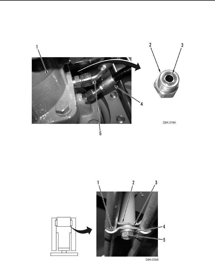
8. Install new O-ring (Figure 20, Item 3) on connector (Figure 20, Item 2), and install case drain hose (Figure 20,
Item 4) on left hydrostatic drive motor (Figure 20, Item 1).
9. Install new O-ring (Figure 20, Item 3) on connector (Figure 20, Item 2), and install brake hose (Figure 20,
Item 5) on left hydrostatic drive motor (Figure 20, Item 1).
Figure 20. Case Drain and Brake Hoses and O-ring.
0157
10. Install clamp (Figure 21, Item 2), washer (Figure 21, Item 3), clamp (Figure 21, Item 1), washer (Figure 21,
Item 4), and bolt (Figure 21, Item 5) on machine.
11. Install crossover tubes. Refer to Crossover Tubes Installation in this work package.
12. Install left bulkhead bracket. Refer to Bulkhead Bracket Installation in this work package.
Figure 21. Tube Clamp.
0157
END OF TASK