
TM 5-2410-240-23-2
0157
RIGHT SIDE ANGLE AND TILT TUBES INSTALLATION CONTINUED
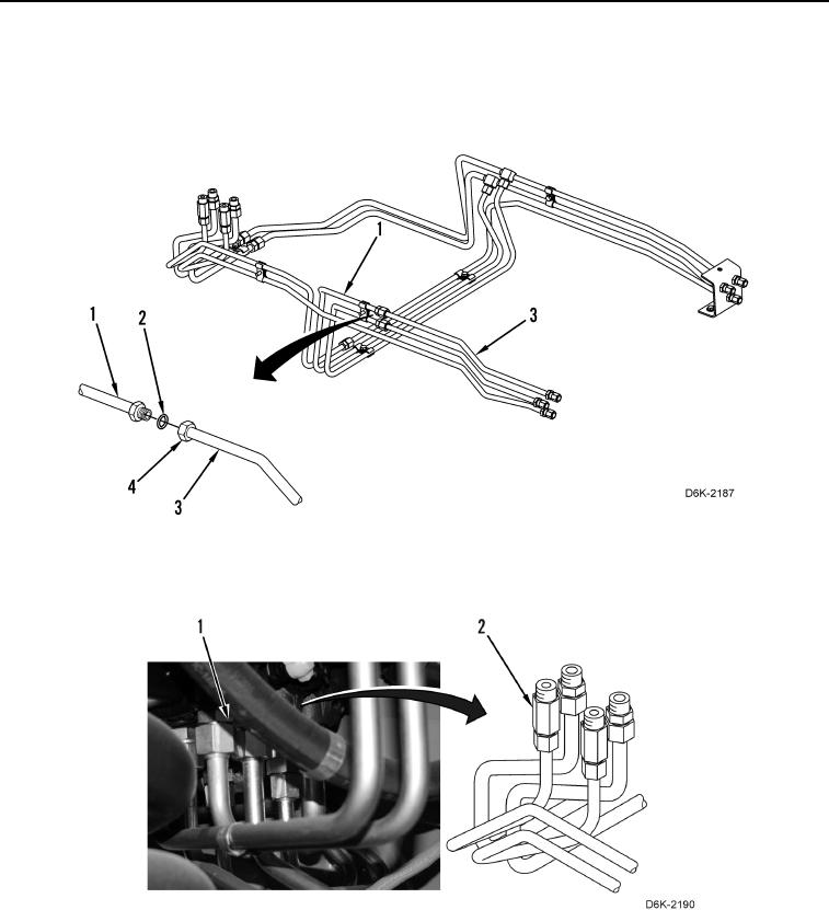
5. Install two new O-rings (Figure 14, Item 2) on two crossover tubes (Figure 14, Item 1).
6. Install two tubes (Figure 14, Item 3) on machine and tighten tube nut (Figure 14, Item 4).
7. Install right bulkhead bracket. Refer to Bulkhead Bracket Installation in this work package.
Figure 14. Right Side Short Tubes.
0157
8. Tighten two tube nuts (Figure 15, Item 2) on valve bank (Figure 15, Item 1).
Figure 15. Valve Bank.
0157
9. Install right bulkhead bracket. Refer to Bulkhead Bracket Installation in this work package.
END OF TASK