
TM 5-2410-240-23-2
0157
BULKHEAD BRACKET INSTALLATION
000157
WARN I N G
Lubricating/hydraulic oils used in performance of maintenance can be very slippery.
Immediately wipe up any spills. Failure to follow this warning may result in injury to
personnel.
N OT E
Hydraulic hoses, tubes, fittings, and clamps are all installed using the same general
method. This procedure covers removal of one hydraulic tube assembly from machine.
Install tubes as noted during removal.
Brackets are all installed using the same general method. This procedure covers
installation of one bracket on machine. Repeat steps to install bracket on opposite side of
machine.
1. Position bracket (Figure 11, Item 4) on three tubes (Figure 11, Item 3) and install two washers (Figure 11,
Item 6), bolts (Figure 11, Item 5), and bracket (Figure 11, Item 4) on machine.
2. Install three bulkhead nuts (Figure 11, Item 2) on three tubes (Figure 11, Item 3).
3. Install three new O-rings (Figure 11, Item 7) and connect three hose fittings (Figure 11, Item 1) to three tubes
(Figure 11, Item 3).
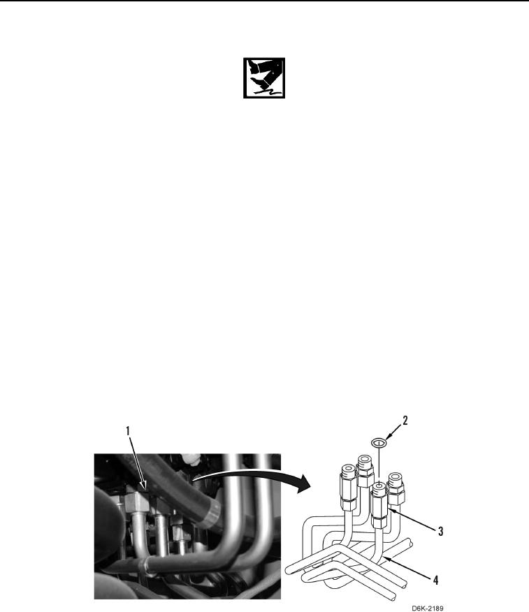
RIGHT SIDE ANGLE AND TILT TUBES INSTALLATION
000157
1. Remove caps and install two new O-rings (Figure 12, Item 2) on two tube nuts (Figure 12, Item 3).
2. Position two tubes (Figure 12, Item 4) on machine and install tube nut (Figure 12, Item 3) on valve bank
(Figure 12, Item 1) finger-tight.
Figure 12. Tube Assembly.
0157