
TM 5-2410-240-23-2
0157
BULKHEAD BRACKET REMOVAL
000157
WARN I N G
Lubricating/hydraulic oils used in performance of maintenance can be very slippery.
Immediately wipe up any spills. Failure to follow this warning may result in injury to
personnel.
C AU T I O N
Cap all hydraulic hose and tube ends along with component connections during removal
to protect against contamination. Failure to follow this caution may cause damage to
equipment.
N OT E
Brackets are all removed using the same general method. This procedure covers removal
of one bracket from machine. Repeat steps to remove bracket from opposite side of
machine.
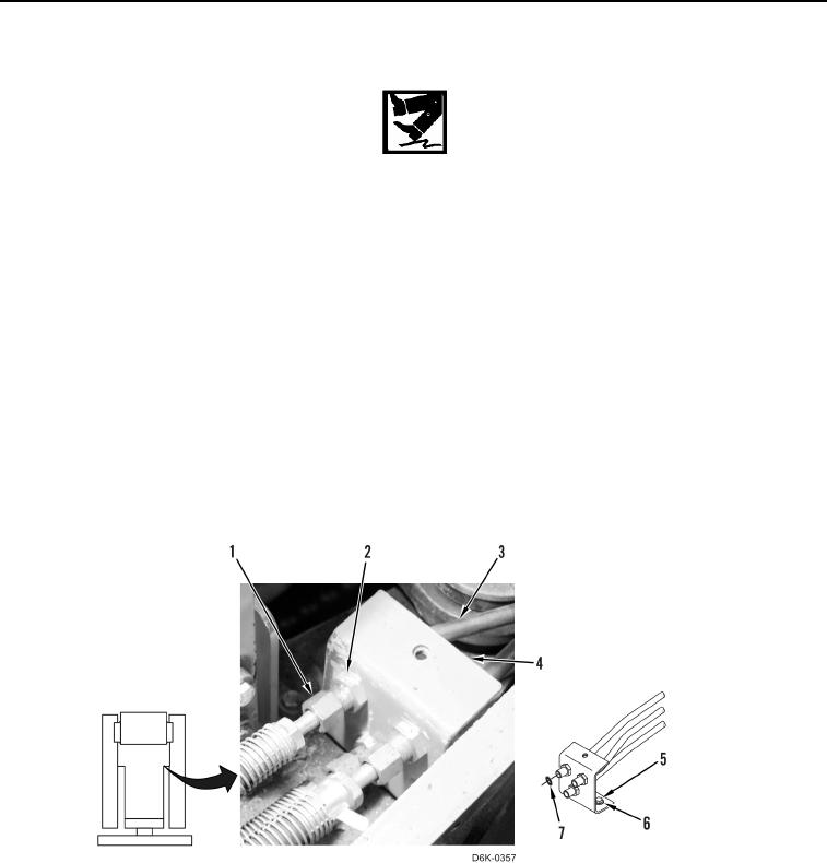
1. Disconnect three hose fittings (Figure 11, Item 1), O-rings (Figure 11, Item 7), and bulkhead nuts (Figure 11,
Item 2) from three tube assemblies (Figure 11, Item 3). Discard O-rings.
2. Remove two bolts (Figure 11, Item 5), two washers (Figure 11, Item 6), and bracket (Figure 11, Item 4) from
machine.
Figure 11. Tube and Bracket.
0157
END OF TASK
CLEANING AND INSPECTION
000157
Clean and inspect all parts IAW Mechanical General Maintenance Instructions (WP 0282).
END OF TASK