
TM 5-2410-240-23-2
0157
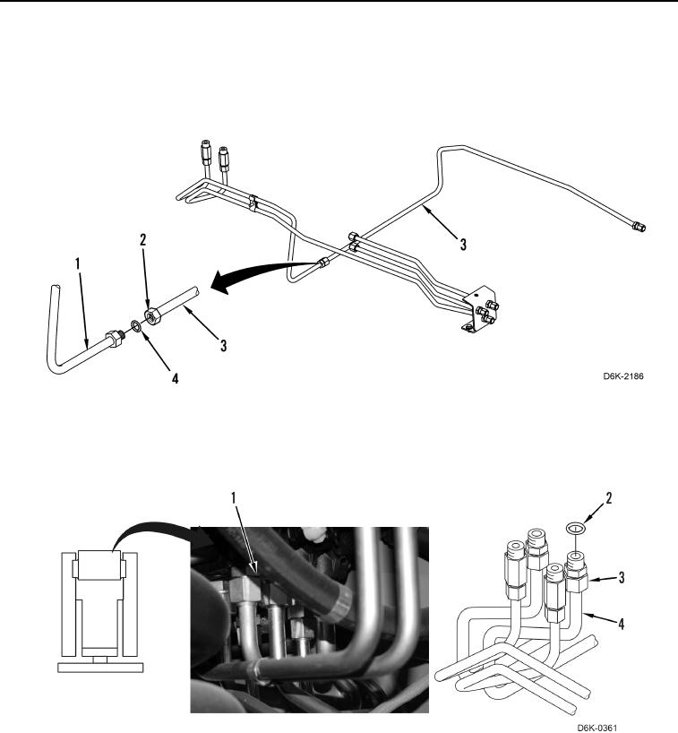
LEFT SIDE ANGLE AND TILT TUBES INSTALLATION
000157
1. Install new O-ring (Figure 16, Item 4) on right side tube (Figure 16, Item 1), and position left crossover tube
(Figure 16, Item 3) on machine.
2. Connect left crossover tube nut (Figure 16, Item 2) to right tube (Figure 16, Item 1) and tighten tube nut
(Figure 16, Item 2).
Figure 16. Left Crossover Tube.
0157
3. Install two new O-rings (Figure 17, Item 2) on two tube nuts (Figure 17, Item 3), position two tubes (Figure 17,
Item 4) on machine, and connect two tube nuts (Figure 17, Item 3) to valve bank (Figure 17, Item 1).
Figure 17. Tube Assembly.
0157