
TM 5-2410-240-23-2
0157
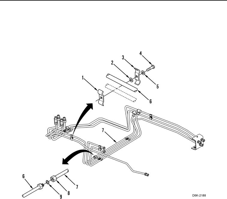
RIGHT SIDE ANGLE AND TILT TUBES INSTALLATION CONTINUED
3. Install new O-ring (Figure 13, Item 9) on tube nut (Figure 13, Item 8) and connect crossover tube nut
(Figure 13, Item 8) to right tube (Figure 13, Item 6) finger-tight.
4. Install clamp (Figure 13, Item 1), washer (Figure 13, Item 2), clamp (Figure 13, Item 3), washer (Figure 13,
Item 5), and bolt (Figure 13, Item 4) securing two crossover tubes (Figure 13, Item 7) on machine. Tighten tube
nut (Figure 13, Item 8).
Figure 13. Right Side Long Tubes.
0157