
TM 5-2410-240-23-2
0157
RIGHT SIDE ANGLE AND TILT TUBES REMOVAL CONTINUED
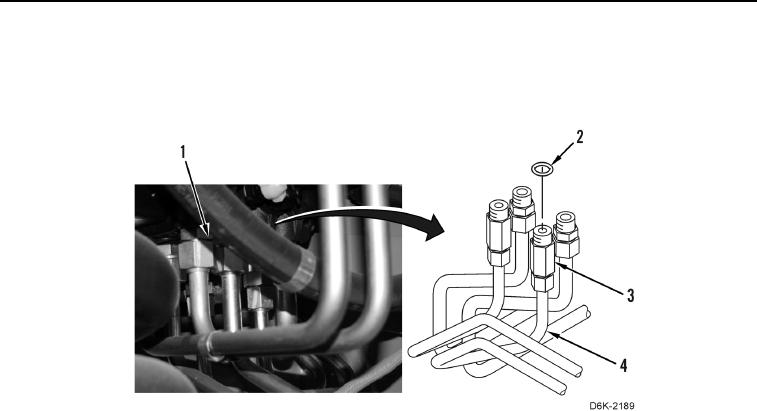
6. Disconnect two tube nuts (Figure 10, Item 3) from valve bank (Figure 10, Item 1), remove two O-rings
(Figure 10, Item 2) from two tube nuts (Figure 10, Item 3), and remove two tubes (Figure 10, Item 4) from
machine. Discard O-rings.
Figure 10. Tube Assembly.
0157
END OF TASK