• Home
  • Download PDF
  • Order CD-ROM
  • Order in Print
Figure 3. Case Drain and Brake Hoses and O-ring.
Figure 5. Tube and Bracket.

Field Maintenance Manual 2 D6K Dozer Type I With Winch and Type II With Ripper
Page Navigation
  1084    1085    1086    1087    1088  1089  1090    1091    1092    1093    1094  
img
.
TM 5-2410-240-23-2
0157
LEFT SIDE ANGLE AND TILT TUBES REMOVAL CONTINUED
N OT E
Note position of tiedown straps to aid installation.
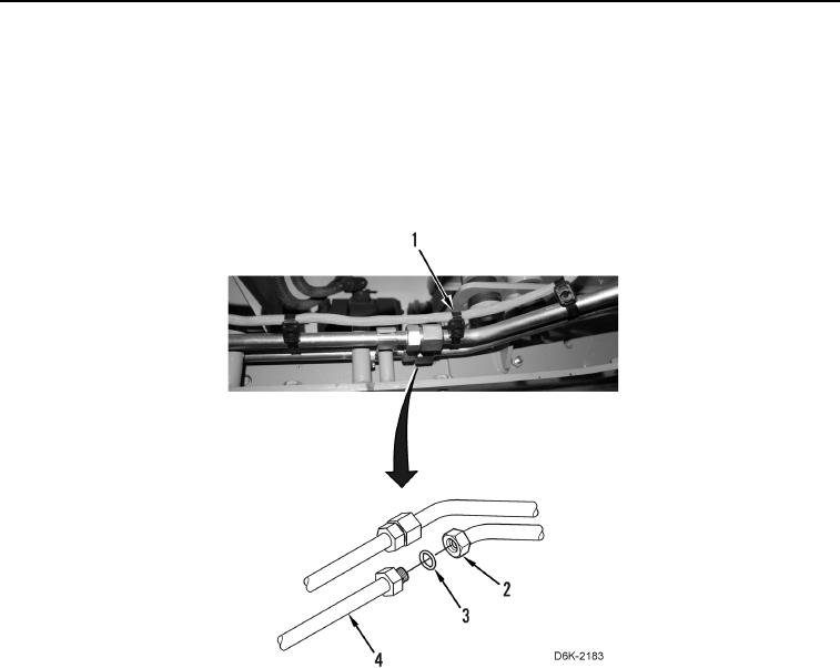
6. Remove three dual tiedown straps (Figure 4, Item 1) from tube. Discard tiedown straps.
7. Disconnect two tube nuts (Figure 4, Item 2) and remove two O-rings (Figure 4, Item 3) from tube (Figure 4,
Item 4). Discard O-rings.
Figure 4. Tube and Tiedown Straps.
0157
0157-6


Privacy Statement
Press Release
Contact

© Copyright Integrated Publishing, Inc.. All Rights Reserved.