
TM 5-2410-240-23-2
0158
REMOVAL CONTINUED
9. Remove nut (Figure 4, Item 1) from adapter (Figure 4, Item 2).
10. Remove accumulator assembly (Figure 4, Item 3) from machine.
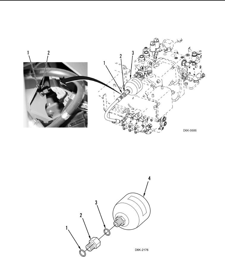
Figure 4. Accumulator Assembly.
0158
11. Remove adapter (Figure 5, Item 2) and O-ring (Figure 5, Item 3) from accumulator (Figure 5, Item 4). Discard
O-ring.
12. Remove O-ring (Figure 5, Item 1) from adapter (Figure 5, Item 2). Discard O-ring.
Figure 5. Accumulator.
0158