• Home
  • Download PDF
  • Order CD-ROM
  • Order in Print
Figure 1. Hydraulic Tank to Valve Bank Hose.
Figure 3. Hydraulic Tank to Accumulator Hose.

Field Maintenance Manual 2 D6K Dozer Type I With Winch and Type II With Ripper
Page Navigation
  1103    1104    1105    1106    1107  1108  1109    1110    1111    1112    1113  
img
.
TM 5-2410-240-23-2
0158
REMOVAL CONTINUED
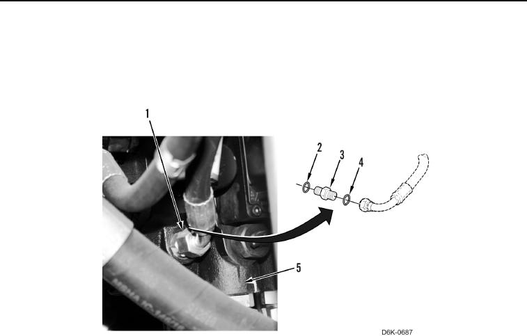
5. Disconnect hose fitting (Figure 2, Item 1) and remove O-ring (Figure 2, Item 4) from connector (Figure 2,
Item 3). Discard O-ring.
6. Remove connector (Figure 2, Item 3) and O-ring (Figure 2, Item 2) from valve bank (Figure 2, Item 5). Discard
O-ring.
Figure 2. Hose and Connector.
0158
0158-4


Privacy Statement
Press Release
Contact

© Copyright Integrated Publishing, Inc.. All Rights Reserved.