
TM 5-2410-240-23-2
0158
REMOVAL CONTINUED
N OT E
Tag all hoses and fittings to aid installation.
Use a container to catch any fluid that may drain from hoses or system. Dispose of fluid
IAW local policy and ordinances. Ensure all spills are cleaned up.
Note routing of hoses to aid installation.
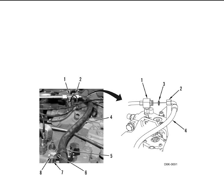
17. Disconnect hose fitting (Figure 7, Item 2) and remove O-ring (Figure 7, Item 3) from tee (Figure 7, Item 1).
Discard O-ring.
18. Remove bolt (Figure 7, Item 6), washer (Figure 7, Item 8), clip (Figure 7, Item 5), spacer (Figure 7, Item 7), and
hose (Figure 7, Item 4) from machine.
Figure 7. Pilot Hose.
0158
END OF TASK
CLEANING AND INSPECTION
000158
Clean and inspect all parts IAW Mechanical General Maintenance Instructions (WP 0282).
END OF TASK
INSTALLATION
000158
1. Remove caps and install new O-ring (Figure 7, Item 3) on tee (Figure 7, Item 1).
N OT E
Install hose as noted during removal.
2. Position hose (Figure 7, Item 4) on machine and connect hose fitting (Figure 7, Item 2) to tee (Figure 7,
Item 1).
3. Install spacer (Figure 7, Item 7), clip (Figure 7, Item 5), washer (Figure 7, Item 8), and bolt (Figure 7, Item 6) on
machine.