
TM 5-2410-240-23-2
0158
INSTALLATION CONTINUED
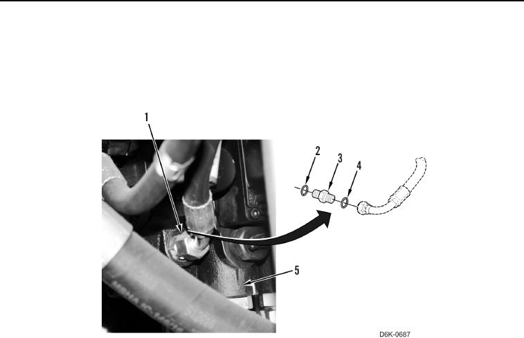
15. Remove caps and install new O-ring (Figure 12, Item 2) and connector (Figure 12, Item 3) on valve bank
(Figure 12, Item 5).
16. Install new O-ring (Figure 12, Item 4) and connect hose fitting (Figure 12, Item 1) to connector (Figure 12,
Item 3).
Figure 12. Hose and Connector.
0158
17. Remove caps and install new O-ring (Figure 13, Item 9) and connector (Figure 13, Item 8) on valve bank
(Figure 13, item 10).